|
NEWSWe specialize in reducing noise emissions and increasing the performance of HVAC and industrial systems.
|
|
In a PV field directly adjacent to a residential area, the operation of the inverters caused noise complaints from residents, especially during the summer months. The dominant sound frequencies of photovoltaic (PV) inverters can be divided into two main ranges: Medium to high frequencies (approx. 200 Hz to 5000 Hz): This range is dominated by fan noise, which is used to cool the inverter. Very high frequencies (approx. 4 kHz to 200 kHz): These frequencies are generated by the internal switching processes of the inverter, by pulse width modulation (PWM) during frequency and voltage conversion. These high-frequency sounds can be perceived as particularly unpleasant, beeping noises. The total sound power of inverters is often in the range of 65 to 84 dB(A). In addition, the reflections of sound from nearby walls cause the noise to spread to more distant areas, which can impair living comfort. One technical problem is that increasing the switching frequency to shift the sound emissions into the barely audible range has a negative impact on the efficiency of the inverter and greatly increases its cooling requirements. The sound enclosure for the 10 inverters has the following dimensions: 11000 x 1800 x 2900 mm (L x W x H). The interior insulation of the enclosure consists of 40 mm thermal insulation and 40 mm sound insulation (StratocellWhisper) on top. All structures for mounting the inverters and routing the cables are also installed in the enclosure. Openings on the underside of the sound enclosure and in the upper area allow fresh air to be supplied and warm air generated by the operation of the inverters to be removed. Although the sound enclosure with RAL-7016 does not have the ideal exterior color to minimize heating from solar radiation, the interior temperature in the enclosure remains around 5 degrees below the ambient temperature thanks to the combination of thermal and sound insulation. This means that the use of the sound hood also prevents temperature-dependent derating, which serves to protect sensitive semiconductor components of the inverter from overheating and causes the inverter to shift its operating point to a lower power level. From an acoustic point of view, it is interesting to note that noise emissions are assessed by the authorities as a total sound level, which significantly reduces the sound reduction requirements as the sound sources are not added together. From a practical point of view, this is nonsense, as the inverters never run in exactly the same operating mode at the same time, so the sound levels should actually be added together (unequal sound source). 
0 Comments
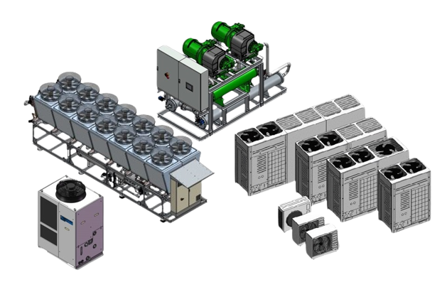
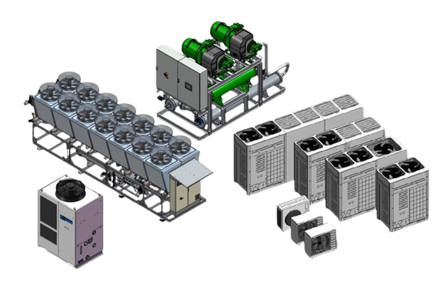
Acoustic enclosures for heat pumps, air conditioning, and refrigeration systems can be ideally integrated into a variety of environments thanks to the free choice of exterior color, usually powder coating. But be careful: in many cases, acoustic enclosures must also be connected to lightning protection. What is often overlooked is that the powder coating has an electrically insulating effect and a very high surface resistance (greater than 1 TΩ), which is why it does not allow electrical contact for lightning protection systems. This greatly reduces the conductivity of the coated surface, and direct discharge of lightning currents via the powder-coated surfaces is not guaranteed without additional measures. To make powder coatings conductive, special so-called dissipative powder coatings (ESD coatings) are used. These contain conductive additives. These reduce electrostatic charge and enable a certain degree of electrical conductivity, which, however, is usually not sufficiently dimensioned or specified for lightning protection systems. For lightning protection applications, this means: 1) Conventional powder coatings prevent a secure electrical connection due to their insulation. 2) Contact points in lightning protection must be mechanically removed from the powder coating to establish metallic, conductive contact. 3) Dissipative powder coatings are a special type, but are rarely used in lightning protection because they cannot safely conduct the high current loads of a lightning strike.  The summer has barely begun when we start rolling out various projects for our acoustic enclosures for large heat pumps. In June 2025 alone, the following acoustic enclosures for large heat pumps will be launched: 1 acoustic enclosure 7,800 x 4,430 x 3,440 mm L x W x H (single enclosure) 1 acoustic enclosure 6,900 x 3,800 x 3,800 mm L x W x H (single enclosure) 1 acoustic enclosure 8,900 x 6,100 x 4,100 mm L x W x H (double enclosure) 1 acoustic enclosure 10,800 x 4,800 x 3,810 mm L x W x H (double bonnet) 1 acoustic bonnet 5,480 x 2,590 x 2,788 mm L x W x H (single bonnet) 1 acoustic bonnet 18,500 x 4,600 x 4,150 mm (L x W x H (triple bonnet) 1 acoustic bonnet 3,100 x 2,200 x 2,472 mm (L x W x H) single hood In total, the 11 large heat pumps are planned to reduce noise emissions by 209 dB(A). All of the systems are located close to sound-sensitive neighbourhoods and cannot be operated without sound measures in compliance with noise regulations. The projects are spread across Germany (Stuttgart, Berlin, Esslingen, Munich), Austria (Innsbruck) and Switzerland (Lucerne). Around 1,350 m2 of 2 mm thick aluminium sheets and around 1,600 linear metres of aluminium profiles plus around 1,300 m2 of insulation were used to produce these acoustic enclosures. In addition, locking systems, sensors and a large number of fastening materials were used.  At a small hospital in France, we installed a sound bonnet for a recooler used to cool the operating theatre and computer tomographs. The acoustic bonnet was required to reduce the noise emissions from the recooler to the bed wing. The recooler moves 28,000 m3/h at full load. The recooler was installed directly adjacent to the plant room on the ground floor. Among other things, 6 heat pump boilers, each with a capacity of 500 litres, are installed in the plant room. The plant room is not heated. The idea quickly arose to use some of the warm exhaust air from the recooler to raise the temperature in the plant room and thus supply the 3,000 litres of service water. As the heat pump boilers use the ambient air, a thermally insulated duct with adjustable louvres was installed directly on the exhaust air side of the acoustic bonnet in order to channel some of the warm exhaust air into the plant room. The free cross-section, which is 1.94 m2 when the louvres are fully open, is designed for full-load operation of the refrigeration system of 28,000 m3/h at an air speed of 4 metres/sec. The position of the louvres is controlled by a pressure and temperature sensor. The louvre position can thus be positioned between 0° and 90°. This reduces the Delta-T for the domestic hot water treatment and achieves a temperature lift of the domestic hot water. Around 1,000 m3/h of air volume is required per heat pump boiler at full load. At full load, the 6 heat pump boilers that provide the service water for the overhead laundry room, sterilisation and kitchen have a total air volume of 6,000 m3/h. To remove the cold exhaust air from the room, a thermally insulated duct with a cross-section of 0.417 m2 was installed, which was connected directly to the exhaust air outlets of the heat pump boilers. This means that all the exhaust air is discharged to the outside. At full load of the 6 heat pump boilers, we have a maximum air velocity of 4 metres/sec in the duct. A load profile measurement, which we will now carry out over the next 12 months, shows how much electricity can be saved in the domestic hot water treatment with this concept. In addition to the noise reduction of the recooler, it has already been achieved that negative pressure and room cooling no longer occur in the plant room when the heat pump boilers are in operation. The following advantages were utilised in this project. Installation of the recooler directly at the smallest possible distance from the plant room and the fact that the heat pump boilers were already in place. Image Legend 1) Heat pump boiler 2) Air inlet duct 3) Water pipe 4) Exhaust air duct 5) Consumer (washing machine etc...) 6) Recooler acoustic bonnet 7) Cold air inlet 8) Hot air recooler 9) Service access in the acoustic bonnet to the recooler 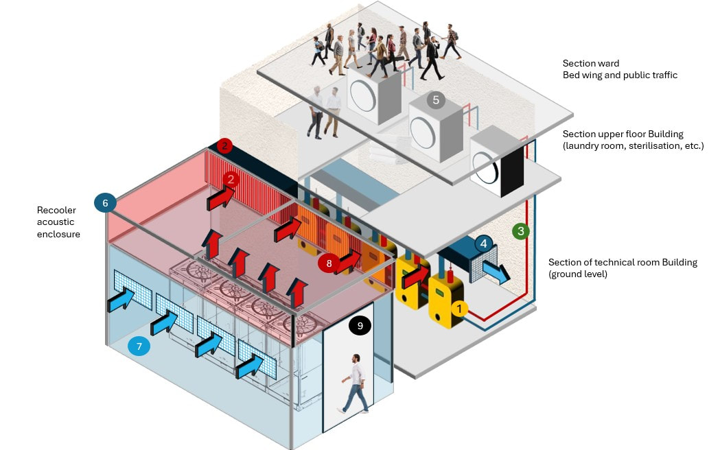 For us, the use of StratocellWhisper with a thickness of 50 mm or more in our sound insulation hoods and sound insulation walls for HVAC systems is undisputed. The material properties and the sound effect speak for themselves. For projects with very high sound insulation requirements, we also install a cavity between the insulation and the external panels.This results in several acoustic and technical advantages: 1) Significantly improved sound absorption: A cavity of 50 mm significantly increases sound absorption, as the distance between the wall and the insulating material acts like a resonator. This means that low-frequency sound waves are better absorbed, and the reflected sound energy is reduced. This is often used specifically in acoustics to increase the effectiveness of absorbers. 2) More efficient use of material properties: Stratocell Whisper is already designed as a sound-absorbing polyethylene foam that offers high sound insulation values thanks to its closed-cell structure. In combination with cavities, the effect of the material is further enhanced, as layers of air act as an additional damping layer. 3) Improved mechanical decoupling: The distance reduces the direct coupling between the wall and the insulating material, which further reduces the transmission of structure-borne sound and vibrations. On the side of the insulating material, we naturally do not cover it with perforated sheets or similar, so that the entire absorption surface of the insulating material is used. Conclusion: A cavity of 50 mm when installing Stratocell Whisper ensures significantly higher sound absorption, improves acoustic effectiveness and offers practical advantages in terms of installation and technical equipment. ity to improve sound absorption 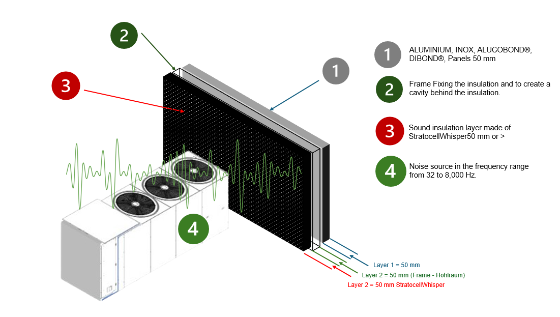 The use of central heat pumps and cooling systems to supply districts or to feed district heating networks is becoming an increasingly important topic. We are talking about systems with very high air volumes and multi-stage compressors. When planning such systems, noise protection is a key issue in both purely residential areas and mixed areas. Passive noise measures such as acoustic enclosures, baffles or baffles can be used to control high frequencies. However, the low sound frequencies between 32 and 500 Hz often become an uncertainty factor during planning when it comes to sound emissions during effective operation. With our latest acoustic enclosures for large projects, we therefore integrate ANC technology directly into our acoustic enclosure design. This allows us to combine passive and active noise protection in our enclosures. The first pilot projects with this combination are now underway. The major challenge we are already seeing today is the rapid adaptation of ANC counter-noise to the rapidly changing operating conditions of the systems, which continuously change the sound field to be reduced. The correct positioning of the sensors and actuators and the rapid processing of a large amount of data (signals) will be the next milestones in practical operation. The combination of IoT, which is now a standard setup for modern heat pumps and refrigeration systems, and AI is the next stage of development for evaluating sensor data for the predictive control of ANC technology. In our opinion, the combination of ANC technology and passive noise control is only worthwhile for large systems at the current state of the art. For smaller systems in small residential buildings, it will take some time before the use of ANC technology can be economically justified. 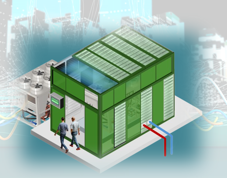 Design of acoustic enclosures for large air-cooled heat pumps and large refrigeration systems.23/3/2025 The design of acoustic enclosures for large heat pumps and large refrigeration systems is based on the following parameters. 1) Physical dimensions of the systems 2) Required air volume at full load 3) Static pressure of the fans 4) Sound insulation to be achieved 5) Access required for service and maintenance work. The following physical parameters must be set in the correct ratio during planning: Air volume / free areas (open Areas) / air velocity / pressure loss. Free air inlet and air outlet areas (net open areas in which the air can enter and exit the bonnet). These open areas must be dimensioned so that an air velocity of 7 metres/sec is not exceeded. This is due to the pressure loss of 28 Pa. at 7 metres/sec. This pressure loss is partially compensated for by the static pressure of the fans, which have to overcome a resistance on the evaporator on the air inlet side and have to expel the air above the fans on the pressure side. Up to an air velocity of 7 metres/sec, the ratio between heat transfer and pressure loss is ideal. At higher air speeds, the heat transfer is negatively affected and the pressure loss becomes too high. In addition, a higher air velocity leads to flow noise which results in an increased noise level. What does this mean for example for the design of a sound bonnet for a system with an air volume of 170,000 m3/h? To calculate the required free area at an air volume of 170,000 m³/h and an air velocity of 7 m/s, the air volume flow must first be converted into the appropriate units in order to then use the formula for the air volume flow. The free area for an air volume of 170,000 m³/h at an air velocity of 7 m/s is around 6.93 m². As the exhaust air and supply air areas are separated to prevent recirculation of the air, the free area of at least 6.93 m2 must be ensured both on the intake side and at the air outlet. 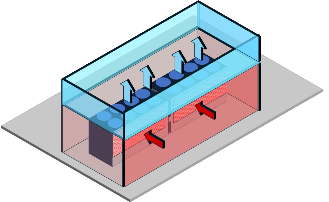 Heat pumps and refrigeration systems are caught between energy-efficient performance and acoustic compatibility with the neighbourhood. A central phenomenon in this context is sound masking effects, which significantly influence both the technical design and the acoustic perception of these systems. These effects result from the complex interaction of different frequency ranges and operating conditions, which often lead to unexpected noise emissions, even if individual components have been optimised. Sound masking effects describe the phenomenon in which the reduction of certain frequency ranges leads to other frequency components being perceived subjectively louder. This effect is based on psychoacoustic interactions: The human ear is less able to localise low frequencies and perceives them as more dominant when the background noise is reduced. With heat pumps, such effects are typically caused by: 1 Frequency overlaps between fan noise (usually medium to high frequencies) and compressor noise (low frequencies), 2 Operating state-dependent modulation as typically occurs during de-icing cycles, in L/W heat pumps where fan speed changes shift the frequency spectrum. 3 Reflection from building structures that amplify certain frequency bands through constructive interference. Air-to-water heat pumps emit sound in the range of 30-70 dB(A), with the critical frequency bands lying between 63 Hz (low humming) and 4 kHz (high humming). Masking effects occur in particular when high frequencies are attenuated by sound insulation measures, making low frequency components more prominent in relative terms. For example, attenuating a 2 kHz signal by 10 dB(A) can result in a 100 Hz hum being perceived as 6-8 dB(A) louder One of the main causes of masking effects are thermodynamically induced changes in operating conditions. At air temperatures around 0°C with high humidity, ice forms on the evaporator fins, which leads to the following effects: 4 Pressure losses in the air flow force higher fan speeds (frequency increase of 15-30%). 5 Compressor load changes when switching to defrosting modes generate pulse-like low-frequency oscillations 6 Material expansion on iced components cause additional resonances in the 80-200 Hz range. These dynamic changes are superimposed on the basic noise spectrum and lead to non-linear masking effects that can hardly be detected by stationary sound measurements. The interaction of these spectra leads to complex superpositions. For example, the 100 Hz component of the compressor can suppress the perception of 800 Hz fan sounds, while at the same time harmonics at 1600 Hz are amplified by resonances in the housing.  The use of AI tools is already saving us a lot of time in the planning, design and production of our acoustic enclosures for heat pumps and refrigeration systems. The calculation of fan key figures, air volumes, pressure losses and, for example, optimum air speeds, can be greatly accelerated through the use of AI. Furthermore, the targeted use of AI tools simplifies the prediction of noise emissions and noise immissions, taking into account various atmospheric and topographical conditions. The use of AI in production serves to optimise the four-cutting of raw materials such as insulation, aluminium sheets and frame profiles, thereby shortening production planning. The use of AI does not solve any questions that cannot be answered without AI, but it speeds up the process of finding answers enormously. Perplexity's announcement to integrate ‘DeepSeek R1’ into its AI platform offers the possibility to access DeepSeek's logical capabilities within the Perplexity framework, which promises to further optimise the performance of AI tools for mathematical and physical problems for the benefit of planning technical building services engineering. 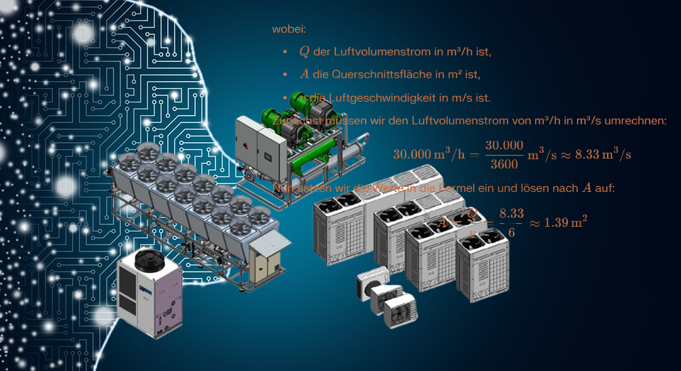 We spent the last two days of January in Hamburg discussing future projects, changes and optimisations in our company. We focussed in particular on current and upcoming projects. We discussed specific optimisation measures to make our processes even more sustainable and efficient, with a focus on the use of AI. The digital integration of production and installers was particularly valuable in order to develop the best possible solutions for our customers. Finally, we visited a property where our acoustic bonnet for two large heat pumps will be installed in the coming weeks - a measure that both reduces noise emissions and optimises energy efficiency. With lots of new impetus and a clear vision, we are motivated to take the next steps.  |
AuthorWe specialize in reducing noise emissions and increasing the performance of HVAC and industrial systems. Archives
August 2025
Categories |
 RSS Feed