|
NEWSWe specialize in reducing noise emissions and increasing the performance of HVAC and industrial systems.
|
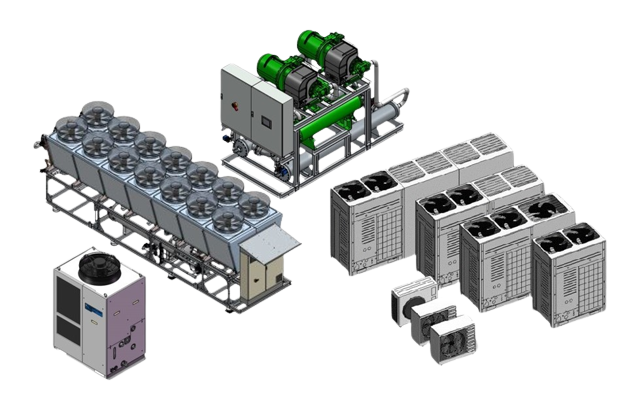
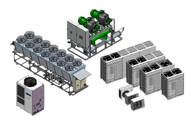
Design of acoustic enclosures for large air-cooled heat pumps and large refrigeration systems.23/3/2025 The design of acoustic enclosures for large heat pumps and large refrigeration systems is based on the following parameters. 1) Physical dimensions of the systems 2) Required air volume at full load 3) Static pressure of the fans 4) Sound insulation to be achieved 5) Access required for service and maintenance work. The following physical parameters must be set in the correct ratio during planning: Air volume / free areas (open Areas) / air velocity / pressure loss. Free air inlet and air outlet areas (net open areas in which the air can enter and exit the bonnet). These open areas must be dimensioned so that an air velocity of 7 metres/sec is not exceeded. This is due to the pressure loss of 28 Pa. at 7 metres/sec. This pressure loss is partially compensated for by the static pressure of the fans, which have to overcome a resistance on the evaporator on the air inlet side and have to expel the air above the fans on the pressure side. Up to an air velocity of 7 metres/sec, the ratio between heat transfer and pressure loss is ideal. At higher air speeds, the heat transfer is negatively affected and the pressure loss becomes too high. In addition, a higher air velocity leads to flow noise which results in an increased noise level. What does this mean for example for the design of a sound bonnet for a system with an air volume of 170,000 m3/h? To calculate the required free area at an air volume of 170,000 m³/h and an air velocity of 7 m/s, the air volume flow must first be converted into the appropriate units in order to then use the formula for the air volume flow. The free area for an air volume of 170,000 m³/h at an air velocity of 7 m/s is around 6.93 m². As the exhaust air and supply air areas are separated to prevent recirculation of the air, the free area of at least 6.93 m2 must be ensured both on the intake side and at the air outlet. 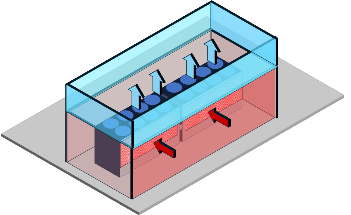
0 Comments
Leave a Reply. |
AuthorWe specialize in reducing noise emissions and increasing the performance of HVAC and industrial systems. Archives
January 2026
Categories |
 RSS Feed