
Planning and designing acoustic enclosures for large chillers and heat pumps with airflows above 100,000 m³/h
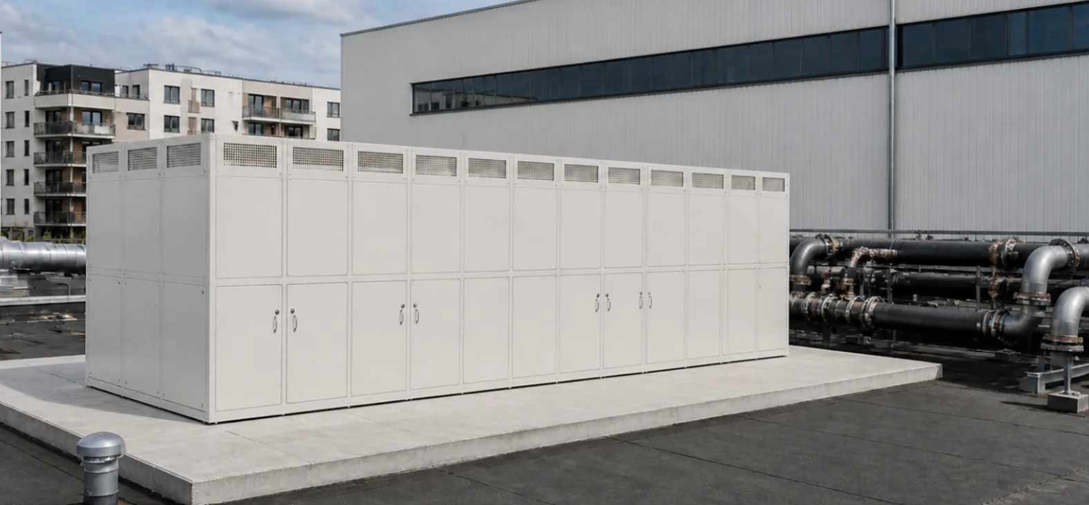
With large chillers and heat pumps moving more than 100,000 m³/h of air, you are always balancing acoustics, aerodynamics, construction and design. At the start of planning, it is therefore advisable to set clear target values for the technical parameters.
Target values at the start of planning
- Target air velocity in the free areas (intake/exhaust): typically 5 to a maximum of 7 m/s. Higher values lead to increased pressure loss, reduced capacity and more flow noise.
- Target noise reduction: about 10–15 dB(A) at the receiver point, with the limits for night-time operation being particularly relevant. Depending on their construction, finished enclosures achieve about 5–18 dB(A) directly at the source.
- Maximum permissible loss of capacity or COP caused by the enclosure: for example less than 3–5 %.
Only once these basic facts are fixed is it worth working out the detailed geometry.
Free areas
The optimum free area follows directly from the required volume flow and the permissible air velocity.
Example: for 100,000 m³/h (≈ 27.8 m³/s) and an air velocity of 4.1 m/s, you need about 6.77 m² of free area per side.
Air velocity, heat transfer and pressure loss
- Air velocity too low leads to a low heat transfer coefficient and a possible loss of capacity.
- Air velocity too high causes a disproportionate rise in pressure loss, higher fan power, additional flow noise and possibly poorer heat transfer (residence time too short, unfavourable distribution).
Enclosure volume, clearances and compaction
Where space for the installation is limited, the achievable envelope area of the enclosure becomes the limiting factor. The internal volume must be large enough for the air to be guided from intake to discharge without extreme deflections. With limited area, the free areas have to be distributed optimally over the envelope. In some cases splitter silencers can then no longer be fitted without creating very high air velocities – resulting in pressure loss and strong flow noise.
Intake and exhaust air must be separated – by partition walls inside the enclosure or separate ducts – so that no recirculation occurs.
Installation and sound bridges
Joints and penetrations, for example for pipework, must be consistently free of sound bridges. Every rigid metal profile connecting inside and outside reduces the sound insulation.
Integration into the surroundings
Especially in residential areas, visual design now carries almost as much weight as the acoustic requirements: reduced, "furniture-like" shapes with clean lines and, ideally, no visible technical add-ons such as ducts or silencers on the outside. More on large systems and cascades under chillers and large heat pumps.
Originally published in German on silent-mode.com