
Noise control for PV inverters: noise emission problems and solutions
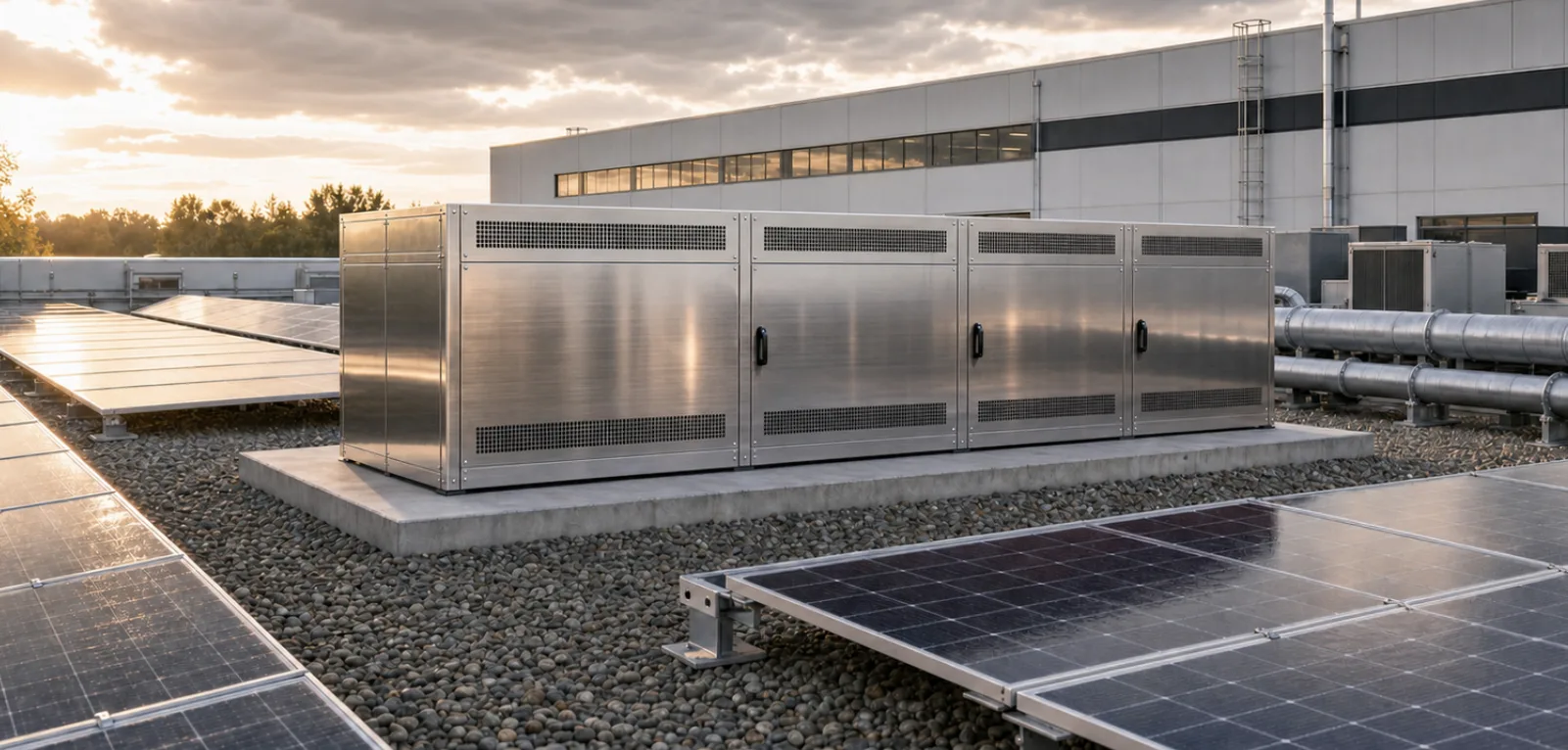
The main causes of noise problems with PV inverters are high-frequency fan noise, switching noise from the inductors and structure-borne sound transmitted into the building. A well-designed acoustic enclosure – including decoupling and thermal air routing – reduces them considerably. Choice of location, vibration isolation and structural screening often help to prevent complaints before they arise.
Typical noise problems with inverters
- Sound level: depending on type and load, approx. 30–63 dB(A) close to the unit; levels rise with the inverter's load.
- Airborne noise: cooling and device fans with broadband noise that is perceived as high-pitched; in addition, switching and inductors (switching frequency, harmonics, occasionally low-frequency hum from grid components).
- Structure-borne noise: with wall mounting, vibrations are transmitted into solid exterior walls and sometimes perceived as a hum indoors or in neighbouring flats.
- Operating profiles: in large PV parks or systems with reactive power compensation, the inverter can also emit noise at night – critical for night-time noise limits.
An often underestimated factor is the combination of a reflective mounting wall and nearby hard surfaces such as courtyards or garages. Reflections can raise the level significantly.
Limits set by noise regulations
- Noise limits depend on the type of area (purely or generally residential, mixed use, outlying areas etc.) and distinguish between day and night.
- Large PV systems with many inverters can require minimum distances similar to battery storage; calculated forecasts with 3D sound propagation are recommended.
- A typical project requirement is compliance with the relevant rating level at the most critical receiver point – often balconies and bedrooms on the first or second floor of neighbouring buildings.
For single systems on residential buildings, the issue is usually not the limit values but perceived annoyance and disputes with neighbours. This calls for a particularly quiet design or retrofitted noise control.
The acoustic enclosure as a solution
An acoustic enclosure surrounds the inverter, reduces the airborne noise radiated by fans and electronics and provides sun protection at the same time. Targeted air routing lets the cooling air enter and leave on the side that is not noise-sensitive.
- Outer shell made of aluminium or galvanised steel, usually powder-coated.
- Inner lining with a highly effective absorber – in our enclosures HSA3, non-combustible to class A1, with no mineral wool and no foam.
- Air openings and, where needed, splitter silencers on the side facing away from the neighbours.
- Sun protection lowers the housing temperature, extends service life and prevents power reduction in hot weather (derating).
- Green roof or additional roof insulation improves sound insulation upwards and reduces heating.
Well-designed enclosures are dimensioned so that the airflow sees little pressure loss and the thermal operation of the device is not restricted.
Important design details
- Acoustics: absorption targeted at the frequency range relevant for fans and electronics (upper mid and high frequencies, plus low-frequency components from grid hum where applicable); no direct sound paths from the device to critical receiver points – using deflections, splitters or L-shaped air paths.
- Thermal: sufficient free ventilation area, where needed ducted inlet and outlet and forced routing of the cooling air in line with the inverter manufacturer's specifications; sun protection through roof overhang, reflective surfaces or green roof.
- Mechanics and service: service doors with quick-release fasteners and a wide opening angle, removable side panels; connection, maintenance and replacement of the devices ideally without dismantling the whole enclosure.
For cluster installations with several inverters side by side, continuous enclosures or container solutions are a good choice, treated acoustically and thermally as one system.
Additional measures without an enclosure
- Optimised location: mounting in cool, quiet places, for example in a plant room or on a side of the building without neighbouring windows; no mounting directly below bedrooms or on hard courtyard walls that act as a reflection trap.
- Vibration isolation: rubber buffers or vibration dampers between inverter and wall against structure-borne sound; check the fixing points so that rigid cable trays or pipe brackets do not short-circuit the isolation.
- Structural screening: small noise barriers or plant containers that interrupt direct sound propagation towards the neighbours – also in combination with PV noise barriers that generate electricity at the same time.
Planning note
When planning large systems, it is worth comparing variants – locations, enclosures, screening – with 3D sound propagation software before the design is fixed. Our standard enclosures for 1 to 5 inverters are described under PV inverters and BESS; the configurator gives you a budget price.
Originally published in German on silent-mode.com